Third-Party RGB LED Controller Wiring for 10" x 10" Infinity Mirror Kits
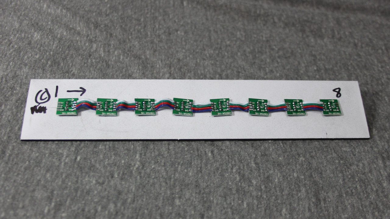
These images demonstrate how to assemble the WS2801 5mm RGB LED Pixels into the inner walls
Not to much detail will be covered, as it is a really simple process. The arrows on the PCBs indicate the direction the data will be sent. Each PCB is chained to the next one in the direction of the arrow. The first PCB will be connected to the controller. The solder pads are really close together and requires careful soldering. The supplied ribbon cable needs to be cut to length, which will be about 0.75", then each end has to be stripped. Stripping the ribbon cable wire without an auto stripper will be difficult, if not impossible.
Click The Images to Enlarge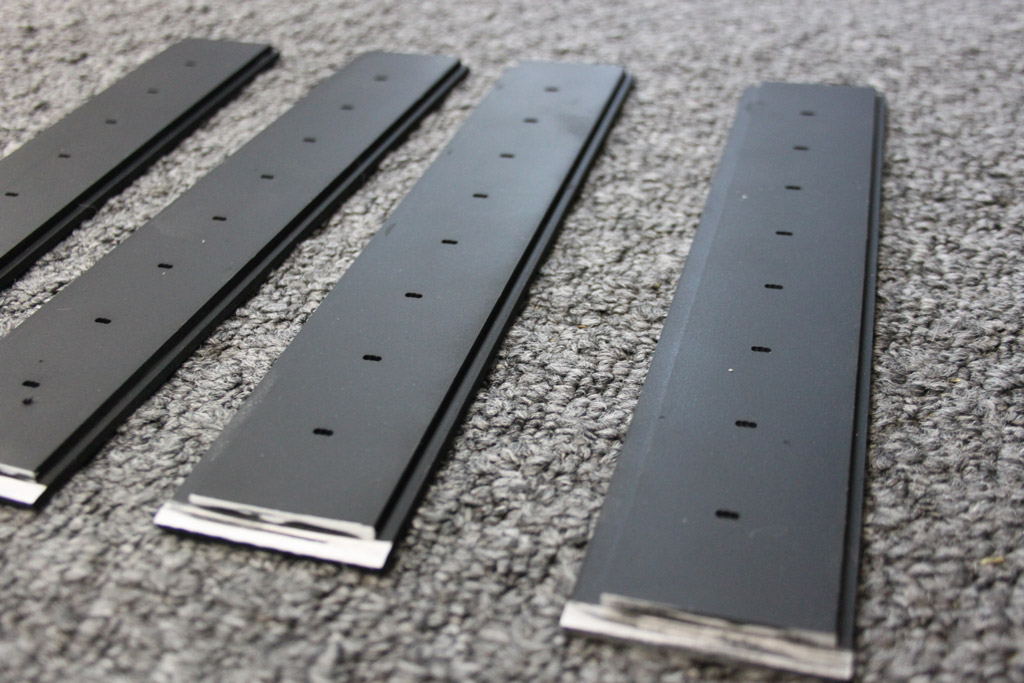 Inner walls come painted and ready to use |
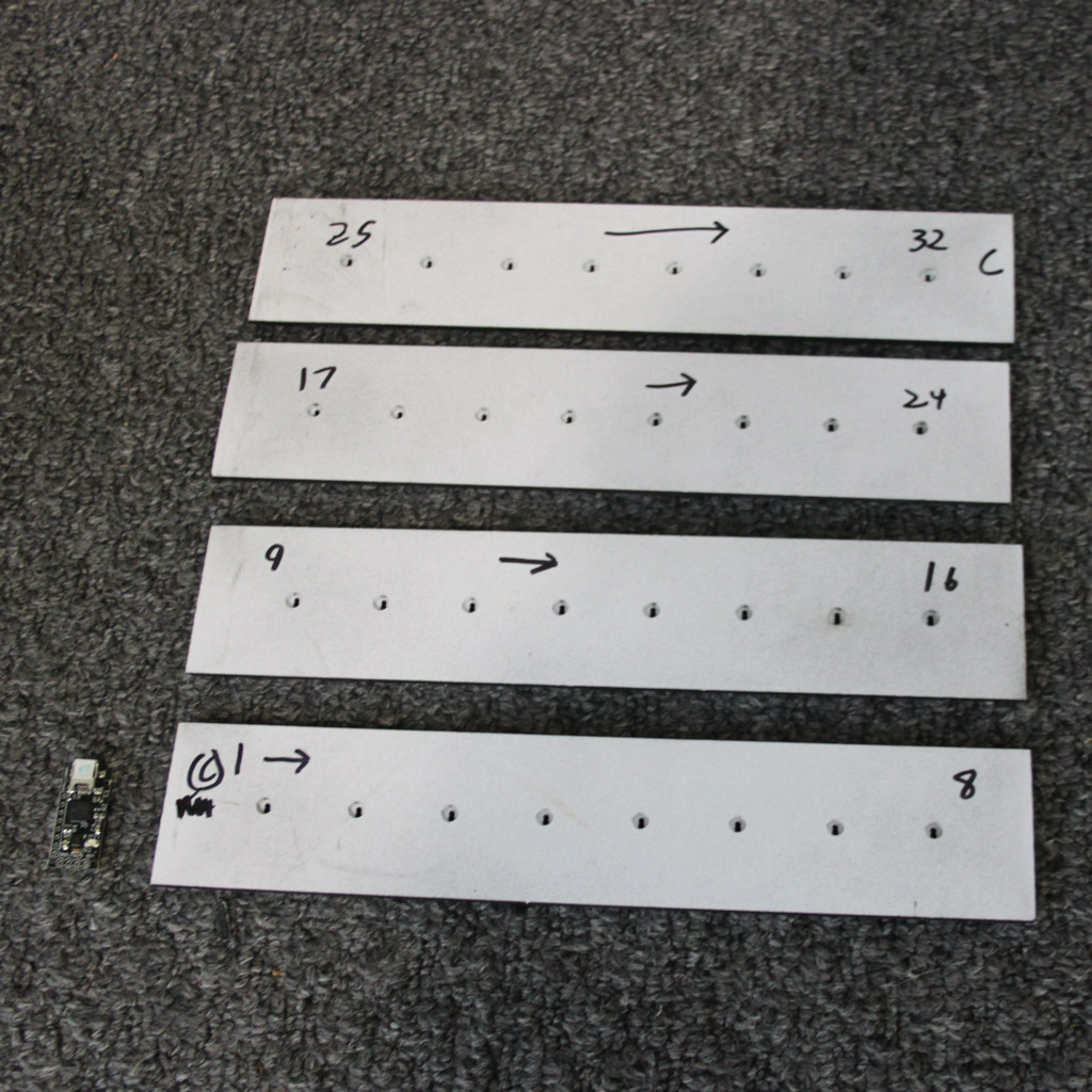 Layout and Mark the Inner walls from the back, numbering and arrows help. |
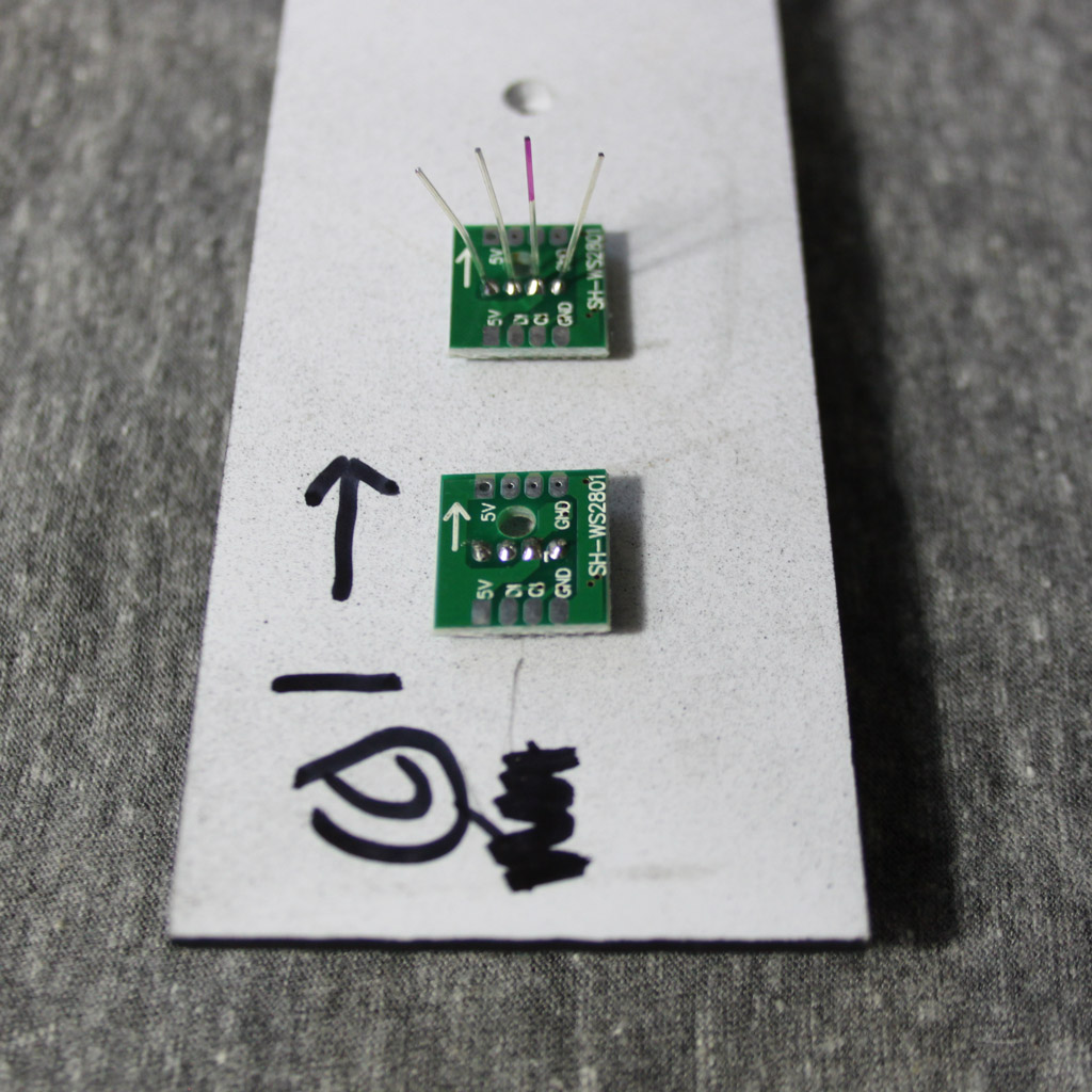 Insert the RGB LED from the black side of the inner walls, the longest lead(marked in red on the imnage) goes into the square PCB hole. Ensure the LED is fitted tight and solder |
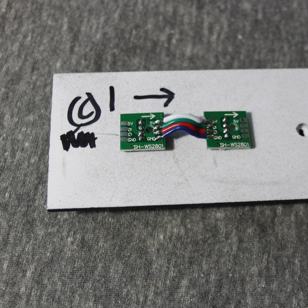 First 2 pixels completed |
 First Inner Wall Completed |
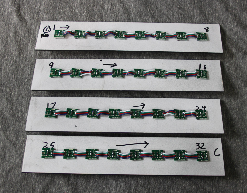 Repeated the pixel installation and wiring for each inner wall |
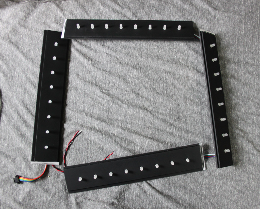 Inner walls wired together, added a 4-pin JST-SM connector to Pixel #1. And added red and black power wires soldered to +5v and GND of the pixel string |
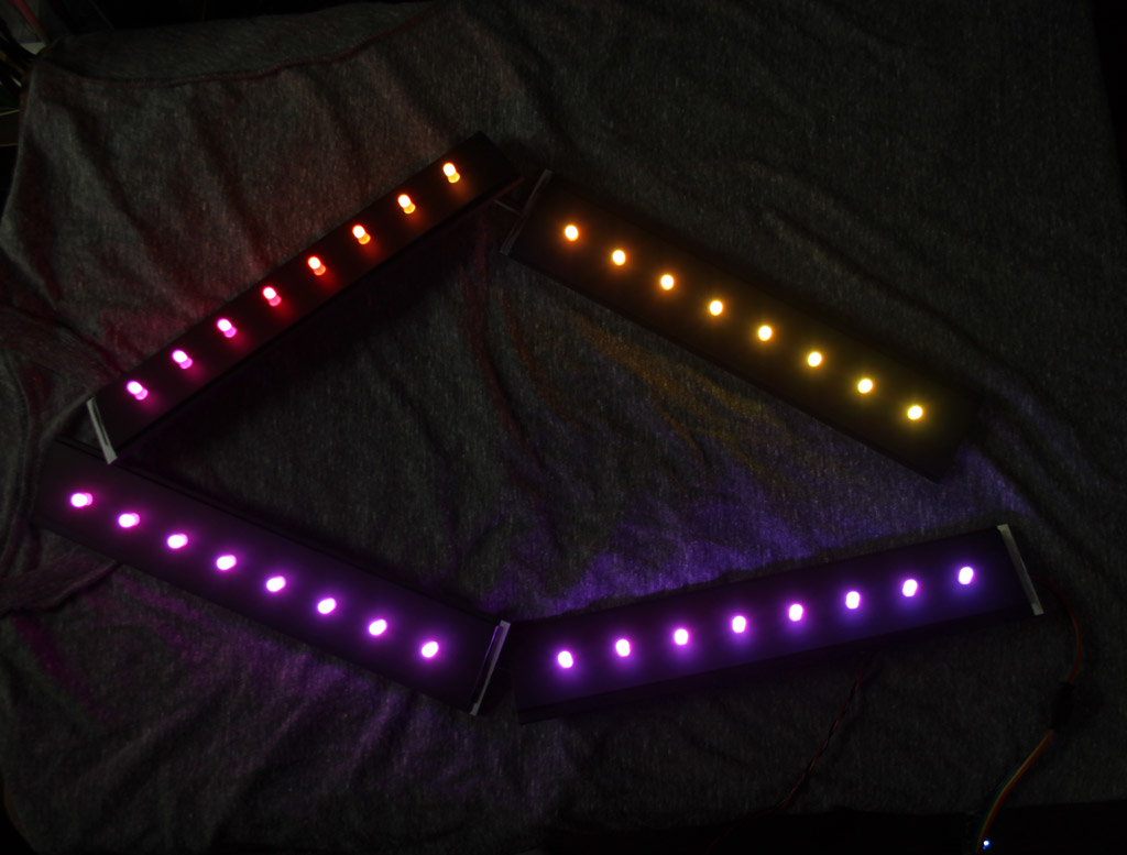 Connected to the controller and power supply. Then power on test after continuity/short testing |