CNC Machine Setup
Setup KCAMIf you are just getting started with CNC Machines, This is a Great Tutorial on Controlling Stepper Motors. Especially the Current Limiting section
If you are using salaved motors and don't know the pinout, visit This Website

1: - Steps/Inch is how many steps it takes your machine to move 1 inch. It can be calculated with the motors rated Degree/Step and the thread size on the axis' threaded rods. See Below for Calibration
Information
- Backlash is the distance that the motors take to reverse the axis' direction. Won't be set unless the axis is loose, or has space to move from up to down.
2: The travel depth is where the Z axis is moved to, while moving the platform from point to point. Normal cut is the depth of a cut or drill when ran from a Excellon or G-code file.
3: Is the Maximum speeds of the axis'. If set to high the motors might skip steps and will not be accurate. Start low then go higher.
4: Ramping, starts the motors slow then increases the speed up to the maximum feed rate. With different adjustment settings.
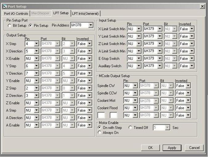

- Make sure the correct Pin Address is selected, check your BIOS to see your parallel port's pin address. User Submitted: Parallel Port PCI Adapter cards for laptops can work by changing the original input/output address. Open YOUR-PATH/KCam4/EXE/Default_Machine.ini in text editor, change the 888 to your paralell port ID number in decimal format. To find it open the LPT1 port properties from Device Manager, click Resources tab, top I/O Range field, left side HEX number(4 digit HEX) is the ID number in HEX, needs to be converted to decimal format.
- Set up the X,Y,Z steps and direction ports.
*Pinout to the left is for the 3 Axis CNC Driver
- Depending on your motor setup, an Axis may need to have its direction inverted.
Setting up Steps Per Inch:
If you know your Motor's step degree, and your setups gear ratio or if using threaded rod, the Threads Per Inch use This Offsite Calculator
One of the easiest ways is to lay graph paper on the bed, hard part is lining the grids up with the X and Y Axis'. Then put a put something with a pointy tip in the chuck(like a nail) to be used as a pointer.
Use the above calculator to get some starting numbers to put in as your Steps/Inch.
Position the Z-axis' pointer on an intersecting set of lines on the bottom left corner of the graph paper.
Use the Command G01 X3 Y3 Z0. To move the pointer to X3" Y3". Mark the point where it should end up on the graph paper, then adjust the steps/inch based on if the pointer came up short or went to far.
Drilling PCBs:
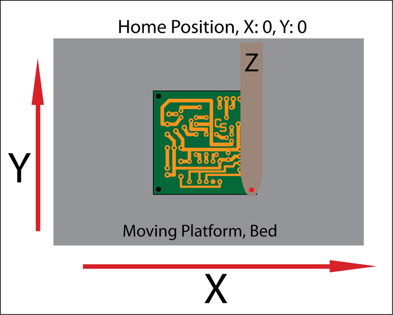
 - Red Dot is the drill/cutting head attached to the Z-Axis.
- The home position is the X0, Y0, Z0 point.
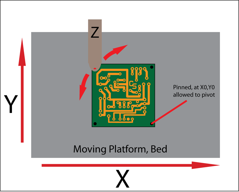
For PCBs:
- The X0, Y0 Point on the PCB is set as the Home Point in the CNC Software.
- The PCB is pinned to the platform at that point, allowed to pivot.
- Software is told to go to the farthest point from Home. The board is then pivoted manually to line up with the drill with the desired location.
- Then the PCB is aligned and square.
- Z Axis is then adjusted so its Normal Cut will drill all the way through but not to far.
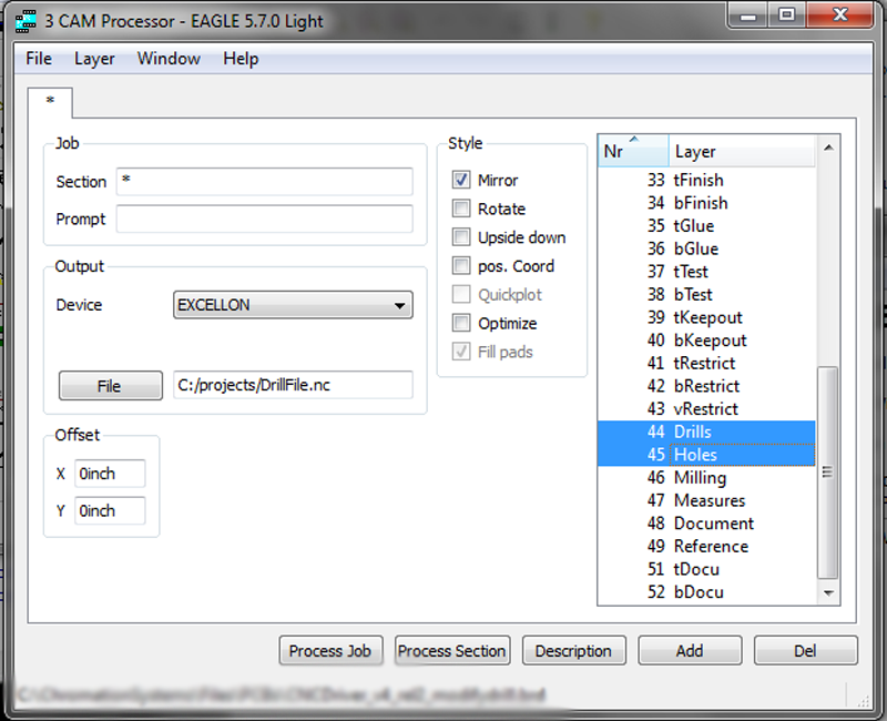
Eagle Excellon Output Options:
- Its easiest to place a hole in a certain amount from each corner, such as 0.25". They are used for orienting the PCB for CNC Drilling then used for mounting the board with screws.
-The "Drills" are part holes and "Holes" are for mounting, they will be the first 4 points in the drill file.
- Selecting "Mirror", allows the boards to be drilled copper-side up, the default is copper side down. Drilling from the copperside allows the drill bit to track into the hole better.
- Select from Device dropdown: Excelleon.
- From the File button select filename and make sure to add .nc to it.
Importing Drill File to KCAM
The drill file needs to be imported from "File - > Import File -> Excellon File"
For whatever reason it always imports for me 10x the size. So goto "Fuctions -> Scale Gcode -> Enter 0.1 for X and Y"
Now the first 4 points for drilling in the Gcode file is the "Holes" used for the mounting and orientation. They should be all offset in from the corner the same amount, such 0.25" from each side of the corner. It has to be offset in KCAM so one of the Holes can be the pivot point to orientate the PCB in the machine. (All the "Holes" should have been drilled with a very small drill bit)
"Fuctions -> Offset Gcode -> X Offset - Add the offset value ex "0.25" - > Y Offset - Subtract offset value ex "-0.25".